


1. Introduction
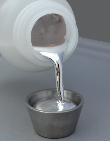
Liquid metals are low-melting point alloys that are liquid at room temperature. This paper will discuss gallium-based liquid metals, the mechanical properties of those alloys, and their usage as a thermal interface material (TIM) in semiconductor applications. When alloyed with tin and/or indium, gallium creates low-toxic alloys that are liquid at room temperature. These alloys have a water-like viscosity but are six times denser than water (Fig. 1). Fig. 1 highlights that LM can be poured like water. Gallium-based alloys also have low-vapor pressure, do not evaporate, and cannot be inhaled. Like other metals and alloys, gallium-based alloys will have high thermal conductivity, which is a highly desirable property for any TIM. Gallium-based liquid metals will wet to almost any surface if they are not heavily oxidized. Since liquid metals are not going through the soldering process, and not making a mechanical bond like soldering paste, it is tough to quantify wettability.

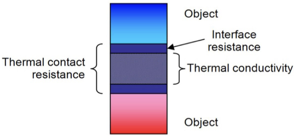
Interfacial resistance and thickness also play a significant role in the TIM’s overall performance. Metals tend to have high-bulk thermal conductivity. They also have incredibly good heat-spreading as well as through conduction. Due to their composition, metals will not dry out over time or degrade in their performance due to temperature changes; however, most metal TIMs are very stiff. This makes it difficult for metal TIMs to make a close connection between the heat source and the heat sink or heat spreader. Overcoming interfacial resistance is the biggest challenge for any metal TIM (Fig. 2).

Since gallium-based liquid metals are liquid at room temperature, they can make a close connection between the surfaces they are connecting. The thermal resistance of any TIM will be defined as:
TIT = BLT/K + RC
Where:
– Total thermal impedance
BLT – Bondline thickness of the TIM
K – Bulk thermal conductivity of the TIM
– Thermal contact resistance at the interface (Fig. 3)

With reasonably high thermal resistance and very low interfacial resistance, bondline thickness does not play a significant role in liquid metal. Even when they are applied in a thicker layer, they can achieve very low thermal resistance (Fig. 4).

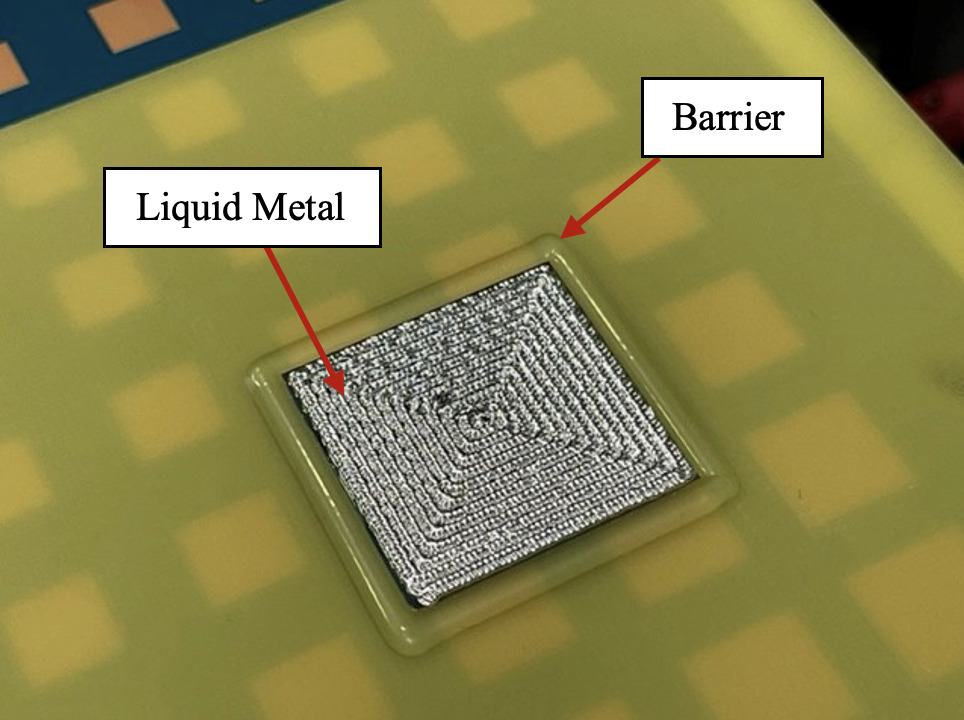
Liquid metals are not only thermally conductive, but also electrically conductive; leaking liquid metals can cause an electrical shortage of electric devices. All liquid metal alloys contain gallium, which can damage some metals, especially aluminum. Another challenge for using these materials is oxidation, as seen in Fig. 5. Passivating oxide layers in liquid alloys causes constant disruption, allowing oxidation of the newly exposed surfaces. Oxidation can degrade thermal contact and reduce the lifespan of the TIM. In order to use liquid metal as a TIM, the liquid metal should be contained to prevent any potential leaking, and nearby components should be insulated. Fig. 6 illustrates one of the solutions for using a liquid metal TIM.

Ga-based LMs are still a quite new type of TIM, and many of the users are unaware of the best way to apply this material in the high-volume production. In this paper, we discuss the necessity of a barrier. Materials used for barriers should be electrically non-conductive. Several types of adhesives and polymers are often used for those barriers. Still, the type of barrier will differ from application to application, and it will be primarily defined by the reliability requirements (TCT, HAST, Thermal shock, vibration, and stress levels). In this case, one UV-cured polymer was used which is non-compressible in nature after UV curing. Barrier material height is defined as an addition of required BLT on top of the thickness of the silicon die to contain that precise amount of liquid metal which is controlled by maintaining the flow rate of the jet valve that is measured through the precision weight measuring scale installed on the dispenser machine. Scenarios like overflow and insufficient material are avoided by the jet valve flow rate control mechanism controlled by software architecture. BLT is decided based on the compressibility of the barrier material which comes from the manufacturer side. Heat sinks are normally screwed in on top to the device. There are a variety of barriers, heat sinks, and the ways that heat sinks could be attached to the chip.
Regarding materials incompatibility, the only material that can’t be used with Gallium based materials is aluminum. With copper, gallium will form intermetallic; however, this intermetallic layer will prevent further dissolution of Cu or Ga, and it will not compromise the thermal performance of the TIM.

Thermal Conductivity
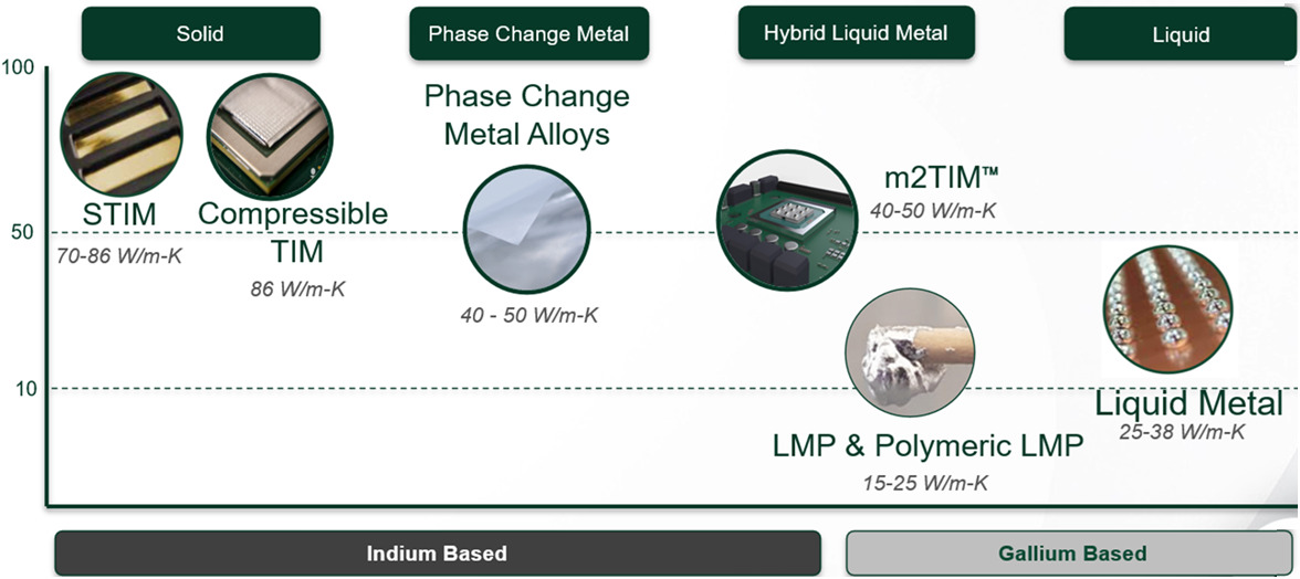
Since the purpose of the TIM is to transfer heat from the heat source to the heat-sink, the thermal conductivity of the TIM plays a big role in the overall performance. Metals and alloys have higher thermal conductivity, which is their biggest advantage compared to other types of TIMs. The thermal conductivity of metals and alloys falls in the range of 15-86 W/m*K, see Figure 7.
Liquid Metal vs. Liquid Metal Paste TIMs
High thermal conductivity would be the greatest advantage of metal TIMs over their non-metal counterparts. However, thermal conductivity is not the only parameter that should be considered when choosing a TIM. Besides thermal conductivity, bondline thickness and interfacial resistance play a role in TIM performance, and interfacial resistance is the biggest challenge for most metal TIMs. Often, metals and alloys are very hard and stiff materials, and it is therefore difficult to ensure that the close connection between heat source and heat-sink materials is maintained. Both LM and LMP TIMs overcome this obstacle since they are in the liquid/paste phase at room temperature, allowing them to adapt to roughness, non-planarity, and any other imperfections in the connecting surfaces.
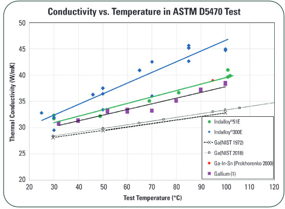
Another interesting property of gallium-based liquid metals is that their thermal conductivity increases with the increase of temperature, meaning that the thermal performance of liquid metal TIMs will improve with increasing temperature (Fig. 8). This test was performed with the standard ASTM D5470 method.
There are several liquid metal alloys that are available on the market now. Table I shows the current most popular liquid metal alloys.
As shown in Table I, Indalloy®300E, eutectic alloy of gallium and indium, has the highest thermal conductivity. On the other hand, Indalloy®306 is very often used in gaming consoles and gaming laptops. This paper will discuss how Indalloy®306 can be applied in high-volume production.
II. Dispensing
Dispensing techniques have evolved from needle contact dispensing methods to non-contact (jetting) dispensing technology. Early dispensing approaches were used for rework applications on components with deficient fills of adhesives onto the substrates or die surfaces. More recently, researchers have proposed the use of dispensing for independent operation of fluids application, such as epoxies, onto the PCB for securing components. Needle contact applications like time-pressure, and rotary auger screw dispensing fall under the same application to dispense the fluid through the needle contact to the printed circuit board.
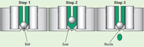
Jetting, as shown in Figure 9, is termed as a technology where material is dispensed as individual droplets onto the PCB through a jet dispenser without any needle contact with the PCB. Jetting technology uses the “ball and seat” mechanism to supply the fluid to the ball seat area with the application of pressure. For this method, as the ball moves in the downward direction to strike the seat, it dispenses the fluid in the form of a droplet onto the substrate (S. Agarwal 2026; Reid et al. 2020).

The time-pressure dispensing mechanism as shown in Figure 10 (a) drives the fluid out of the needle through application of pressure onto the syringe. The fluid will stop dispensing from the needle as the applied pressure is switched off from the actuator. In rotary auger-screw dispensing, shown in Figure 10 (b), the fluid is moved along the cartridge by the rotary motion of the helical auger screw controlled by the driven motor through application of pressure onto the syringe and finally driving it out of the needle. It is generally used for high viscosity applications due to steady movement of the fluid through the cartridge and developed high pressure at the bottom of the cartridge due to a shearing force because of the rotary motion of the auger. Jetting works mostly on the principle of positive-piston displacement fluid dispensing (Figure 10 (c)) which involves a mechanism of pushing the fluid along the cylinder chamber through the reciprocating motion of the piston which forces the material out of the needle. Herein, the piston and cylinder are the two essential components in this driving mechanism.
Although all three of them dispense fluids, each uses a slightly different approach and so is better suited for some applications than others. The time-pressure mechanism is used for a higher variety of situations due to its low maintenance, cost, and ease of operation. However, it is difficult to control due to the amount of pressure variability in the syringe, which can affect the dispensing quality and consistency. Also, the fluid tends to drip from the needle tip due to build up residual back pressure from the fluid. Both time pressure and rotary auger-screw have no inbuilt mechanism to seal the fluid chamber at the needle end in comparison to jetting where ball sits onto the seat to seal the fluid chamber.
_time-pressure_(b)_rotary_auger-screw_(c.png)
The dispensing of fluid volumes in short bursts of applied syringe pressure makes the application process unpredictable as the flow rate of the fluid is time dependent with time-pressure. Rotary auger-screw tends to agitate some of the materials inside the helical groove which leads to clogging issues. Time-pressure dispensing has been the main area of attraction for the past twenty years, but to mitigate the drawbacks must evolve from needle contact dispensing to jetting technology. Jetting involves tapping of the piston with a ball end onto the conical seat opening to eject a droplet at a constant volume in a more repeatable and precise manner resulting in good dot quality at a particular syringe pressure. Jetting works much faster than traditional methods like time pressure or rotary auger as it involves Z-axis movement very close to the substrate to form a droplet. When LM is applied by jetting, it wets the surface way better than when the material is dispensed by traditional techniques like time-pressure or rotary auger pump. Liquid metal has been feasible in mainstream applications nowadays which involve graphics processing units (GPU), central processing units (CPU) either on laptops or gaming consoles. A more thermally efficient TIM which is called liquid metal conducts the heat out of the processor to the heatsink on a level of 17 times faster than the traditional thermal interface materials (Prescott 2023). Liquid metal is applied manually with minimal level of automation these days to maintain the required bondline thickness with challenges. Bondline thickness plays a very crucial factor in having the components packed tight enough, so the final product could be as thin and light as possible. A tiny non-conductive barrier is required to contain the electrically conductive liquid metal to avoid any short circuits.
III. Experimental Methodology and Analysis
A. Objective
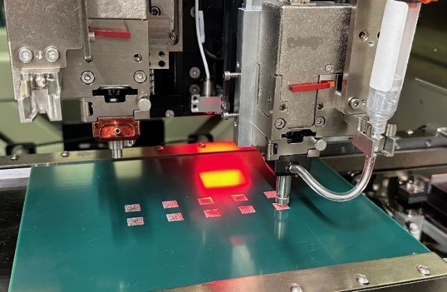
The main objective of this research is to conduct a detailed study to repeatedly dispense a liquid metal to understand the dispense characteristics like weight repeatability and dispense performance. The study involves the use of a high-speed dispensing system i.e. ITWEAE Camalot Prodigy with a NanoShot piezoelectric jetting pump installed which can dispense material in a repeatable manner without affecting the dot quality. Indy alloy number 306 packed in cartridge sizes of 10cc was used for this study.
B. Experimental Set up
The sample fire-resistant (FR4) green substrate as shown in Figure 11 was used to simulate a 10 x 10 millimeters rectangular pattern very similar to the one used in high-speed computing applications involving GPUs and CPUs. A weigh measuring cup placed onto the high precision weight measuring scale was used for pre-weighing the sample to ensure dispensing volume is tightly controlled before dispensing the rectangular pattern onto the FR4 substrate.
NanoShot jetting pump is set up by dispensing a 10x10 millimeters rectangular pattern with a 100-micron precision needle tip. The pump makes an adjustment based on the target total weight with defined process tolerance of ±5 percent to adjust the number of extruded droplets to dispense the correct amount of material into the weight-measuring cup followed by deposition onto the FR4 substrate.

The standard process program involves dispensing the target total weight of 100 milligrams into the weight measuring cup, cleaning the needle, sensing the height of the substrate, and then dispensing the rectangular pattern onto the FR4 substrate. Target total weight for liquid metal (LM) weigh repeatability on the weight precision scale on the machine was defined as 100 milligrams with process tolerance of ±5 percent while the pattern weight on FR4 substrate was targeted to 200 milligrams total weight. Weight repeatability is performed by dispensing individual droplets from the jetting pump positioned over the weight cup at a vertical Z-distance onto the precision weight scale installed on the dispenser machine. Surface flatness or profile has no effect on weight repeatability.
C. Weight Repeatability Analysis
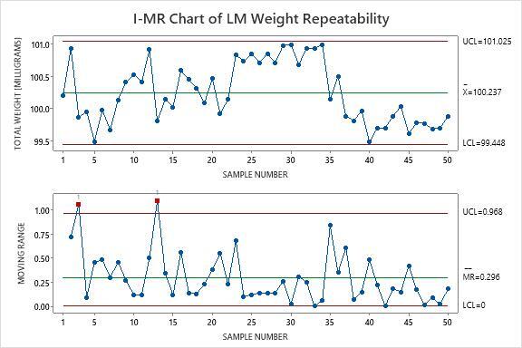
Control charts are used to determine the variation in the process for analysis purposes. Laboratory testing environments frequently employ I-MR charts for individual test results, especially when testing costs or time constraints prevent multiple samples per time period. The moving range calculates the absolute difference between consecutive measurements, creating a measure of short-term process variability. Similarly, automated manufacturing systems that collect continuous data streams benefit from Individual Moving Range charts monitoring capabilities. Figure 12 shows the Individual and Moving Range control chart created on Minitab statistical software for liquid metal weight repeatability into the weight scale cup. The sample size was chosen to be 50 for this study. Centerline on the I-chart is the average of individual weight samples collected. Lower and Upper Control limits are defined as three standard deviations on either side of the centerline. The individual chart for liquid metal weight repeatability shows no points fall beyond the 3 standard deviation control limit which reveals a stable process (S. Agarwal and Lazic 2024). Two test points fall outside the control limits on the moving range (MR) chart. This indicates special cause variation which may be due to the compressible nature of the material which leads to slightly big deviation from one sample to the other.
_weight_repeatability_with_a_piezoelectric_jetting_pump.jpg)
Test Results for MR Chart of LM Weight Repeatability
TEST 1. One point more than 3.00 standard deviations from center line.
Test Failed at points: 3, 13
There will be lot-to-lot variations depending on how the material is packed. Any air bubbles captured during packaging would come up to the surface and would be eliminated at the material manufacturer’s end. Droplet weight variability could be handled by the auto-correction weight calibration through the precision weight scale installed on the machine.
D. Process Capability Analysis
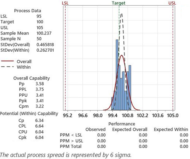
For the interpretation of process capability statistics, the data should approximately follow a normal distribution. Cp indices recognize the fact that the samples represent rational subgroups, which indicate how the process would perform if the shift and drift between subgroups could be eliminated. Therefore, it calculates process spread using within-subgroup variation. Process capability index, Cpk measures how close the process is to the target and how consistent the process is around its average performance. An operator may be performing with minimum variation, but he/she can be away from his/her target towards one of the specification limits, which indicates lower Cpk, whereas Cp will be high. For both the shifts, high value of Cp and low value of Cpk indicate that the process has a centering problem (S. Agarwal 2016; Sunny Agarwal 2024a). A generally accepted minimum value for the indices is 1.33 according to industry guidelines to determine whether the process is capable or not (Sunny Agarwal 2024b; S. Agarwal and Lazic 2025). Figure 13 shows that both tails for target total weight of 100 milligrams fall inside the specification limits for tolerance level of ±5 percent at 6 sigma capability.

E. Bondline Thickness Analysis (BLT)
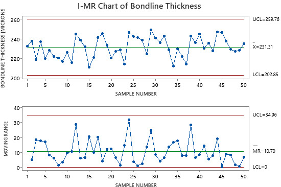
The thickness of a bond line is crucial, especially for liquid-dispensed materials, as it varies based on the stand-off in each application. While minimum bond line thickness is emphasized in part specifications, it is frequently neglected and not properly managed during the process and manufacturing engineering stages. Inadequate bond line thickness poses risks such as low strength, subpar electrical properties, and increased thermal resistance. Bondline thickness of 225 ± 25 micron was required for a gaming consumer application to maintain a dispense weight of 200 milligrams across the 10x10 millimeters rectangular chip. A solder paste inspection (SPI) system is used to measure the bondline thickness across a sample size of 50.

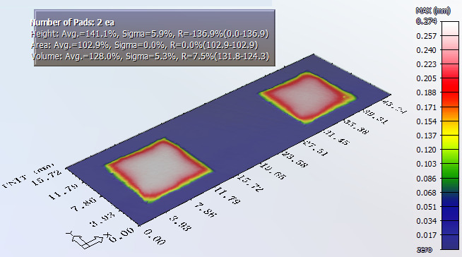
Figure 14 shows both individual and moving range charts for bondline thickness have no points falling beyond the 3 standard deviation control limit which reveals a stable process. Figure 15 shows the profile measurements of bondline thickness across 2 pads placed next to each other. Average bondline thickness across those pads came out to be around 230 microns which is very close to the desired target of 225 microns.

IV. Conclusion
With their unique properties, liquid metals are one of the best options for TIMs. Just like any other metal, they have high thermal conductivity, but since they are liquid at room temperature, they can adopt any imperfections of the surfaces they are connecting, and they don’t need to be compressed with high pressure to achieve very low thermal resistance. Even though the BLT of LM will not affect the overall thermal performance of LM thermal interface material, it’s very important to keep volumes in certain ranges, and that is why having a uniform BLT is crucial. With this study liquid metals have also been proven to have achieved desired bondline thickness with good control on dispense volume for high volume assembly production.
Acknowledgment
The authors would like to thank Mike Butler from Parmi USA for their assistance with the research for this paper.