
I. Introduction
Wire bonding has been the dominant interconnection method in microelectronics for over five decades, offering low cost, high throughput, strong electrical performance, and adaptability across package types from traditional dual-in-line packages (DIPs) to fine-pitch surface-mount and multi-chip modules (Chauhan et al. 2017). Despite the rise of advanced interconnects such as flip-chip and TSV-based 2.5D/3D integration, wire bonding remains essential for high-reliability, cost-sensitive applications in automotive, industrial, and consumer electronics (Li and Goyal 2017). As a mature, efficient process, it enables trillions of electrical and mechanical connections at high production speeds and near-perfect yields (Zhou et al. 2023; Harman 1997). Among the various wire-bonding techniques, ultrasonic wedge bonding, particularly the second bond or “stitch bond”, plays a critical role in completing the electrical path from the die to the leadframe or substrate (Charles 2010; 2016; Ji et al. 2006). Unlike ball bonding, which is initiated on a pristine die pad, the second bond (wedge) is formed on a leadframe that has already been subjected to thermal exposure. This site is specifically vulnerable to interfacial oxidation, which can impede metallic diffusion and lead to premature failure under thermal and environmental stress. Therefore, ensuring robust bonding strength is critical for long-term package reliability (Charles 2016).
The Quad Flat Package (QFP) remains a widely adopted format in high-volume semiconductor packaging due to its low cost, ease of board-level assembly, and suitability for medium- to high-I/O-count devices. In QFP designs, leads extend outward from the package body, with wire bonds typically routed from the die center to the peripheral leadframe paddles (Rezvani et al. 2013). Cu-based leadframes (Cu-LFs) are widely used in QFPs alongside silicon dies, bonding wires, and epoxy molding compounds due to their superior electrical and thermal conductivity and lower cost. Compared to traditional iron-based alloys such as Alloy 42 (Fe-42 wt% Ni), they are preferred for plastic IC packages (Cho and Paik 1998). As the semiconductor industry advances toward finer pitches, thinner profiles, and higher operating currents, the second bond in QFPs formed at the leadframe becomes increasingly critical. This site is particularly susceptible to mechanical and electrical stress, especially in automotive-grade applications where extended exposure to high temperatures is common (Razali et al. 2018).
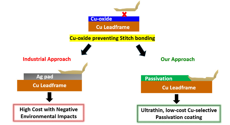
Metal-plated leadframes are commonly employed to enable reliable second-bonding in QFPs and other advanced packaging formats. These leadframes typically feature a 5-12 µm thick Ag layer deposited over a Cu substrate (Li and Ong 2012; Li 2009). The Ag layer serves dual purposes: it acts as a bondable surface for wedge (stitch) bonding and functions as a diffusion barrier, delaying oxidation of the underlying Cu during thermal processing (DiGiacomo et al. 1974). While Ag plating has been widely adopted in industry, it presents several limitations. (a) Ag is an expensive noble metal, and its use over a large area significantly increases material and processing costs. (b) Ag is associated with environmental and regulatory concerns, including its bioaccumulative nature and challenges in industrial waste management (Padhye et al. 2023). Lin et al. have also shown that Ag is not an effective long-term barrier against Cu diffusion (Lin et al. 2002). During high-temperature steps such as die attach (~175 °C) and second wire bonding (~200 °C), Cu migrates through the Ag layer, forming oxide-rich Cu domains at the bond interface. These oxides interfere with metallurgical bonding, reducing pull strength, interfacial delamination, and early-life reliability failures. Alternative metallization strategies have been explored. Among them, Ni plating has received attention for its ability to retard Cu diffusion (Okamoto et al. 2004). However, Ni-plated Cu leadframes exhibit poor interfacial adhesion, particularly at the Cu-Ni and Ni-Ag interfaces, leading to mechanical instability and delamination during thermal cycling. Moreover, both experimental and microstructural analyses have demonstrated that Cu can still diffuse through Ni layers, especially at elevated temperatures, thus undermining its long-term effectiveness as a diffusion barrier (Zhang et al. 2014; Pinnel and Bennett 1976). These studies collectively emphasize that conventional metal-based diffusion barrier systems (Ag, Ni) are inadequate for preventing Cu migration and oxidation during extended thermal exposure.
To address these limitations, we developed a Cu-selective passivation strategy based on the surface modification of Cu substrates The proposed strategy illustrated in Fig. 1 offers two critical advantages: (1) it effectively suppresses Cu oxidation at elevated temperatures (~200 °C), thereby enabling robust Cu-Cu stitch bonding, and (2) it provides a low-cost, environmentally sustainable alternative to electroplated Ag pad, aligning with industry trends toward green and cost-efficient packaging solutions. In our recent study (Alptekin et al. 2023), we demonstrated that a 10 nm Cu-selective passivation layer significantly reduced Cu (I) oxide (Cu2O) formation by up to 75% during thermal annealing at 200 °C in ambient air. This was confirmed via Reflection Absorption Infrared Spectroscopy (RAIRS) and Quartz Crystal Microbalance (QCM) measurements. The passivation coating enabled >99% Cu-Cu ball bonding yield, with minimal non-stick-on-pad (NSOP) defects and shear strengths surpassing those of conventional Cu-Al bonds. Furthermore, in accelerated corrosion tests conducted in 100 ppm chloride solution, unprotected Cu-Al wire-bonded devices exhibited complete wire lift-off within hours. In contrast, Cu-Cu bonded samples coated with our passivation layer remained structurally intact even after 40 days of immersion in a 100 ppm chloride solution, demonstrating the coating’s corrosion-inhibition properties and suitability for automotive-grade, high-reliability applications.

Building on the success of our Cu-selective passivation in ball bonding, we extended the study to stitch bond the critical second bond in quad flat package (QFP) assemblies. We evaluated two industry-standard wires: 25 µm aluminum (Al–1wt%Si) wire for cost-effectiveness, and palladium-coated copper (PCC) wire for enhanced reliability (Zhang et al. 2023). Bonding was performed on bare and passivated Cu leadframes that were pre-annealed at 170 °C-200 °C to simulate typical wire-bonding conditions. With Al wire, passivated Cu-LF showed significantly higher pull strength and interfacial integrity than bare Cu-LF, with failure shifting from the bond interface to the wire neck, indicating strong adhesion. Similar trends were observed with PCC wire bonded at 125 °C and 200 °C, where passivated Cu-LF again outperformed bare Cu-LF in pull strength. These results confirm the effectiveness of passivation in enabling reliable, Ag-free stitch bonding across different wire materials and bonding conditions.
II. Experimental
A. Surface Activation and Coating of Cu-Leadframe Substrates
Cu-LF substrates provided by our industrial collaborators were used throughout the study. To remove surface contaminants and activate the Cu surface, the substrates were treated with a reducing plasma (95% Ar and 5% H₂) at different gas flow rates in standard cubic centimeters per minute (SCCM), controlled using the PROTEK PC-540 MFC readout instrument. Harrick Plasma PDC-001, a benchtop plasma cleaner was used to perform the plasma treatment before the coating process.
B. Wire Material Used for Stitch Bonding
Stitch bonding was performed using 25 µm (1 mil) diameter aluminum (Al-1 wt% Si) wire and palladium-coated copper (PCC) wire (4N Cu, 99.99%) with a Pd coating and gold flashing. The materials were sourced from AMETEK Engineered Materials and Topline (Tanaka) Corporation, respectively.
C. Conformal Coating on the Cu-Leadframe Substrate
Using a previously established liquid-phase deposition method, an ultrathin Cu-selective passivation layer was applied to Cu-LF substrates (Durai et al. 2024). To examine how passivation film thickness affects bonding performance, we prepared samples with varying thicknesses and systematically characterized them.
This study employs attenuated total reflectance (ATR) spectroscopy to quantify the thickness of the passivation layer. The chemical characteristics of the passivation coating were further analyzed using a Bruker Vertex 70 spectrometer equipped with a Platinum ATR Diamond F Vacuum accessory and a deuterated triglycine sulfate (DTGS) detector. Surface roughness and coating conformality were evaluated using a Nanosurf Mobil S Atomic Force Microscope (AFM) in contact mode and an in-house-developed rapid micro-screening test based on decorated Cu grain etching (Kumaravel et al. 2024). Scans were acquired over a 10 µm × 10 µm area at a 256 × 256-pixel resolution. Roughness parameters were extracted using Gwyddion software with at least three spots per sample to ensure reproducibility.
D. Studying Cu-oxide Suppression at High Temperature
To evaluate oxidation suppression capabilities, both passivated Cu-LF with varying coating thicknesses and as-received Cu-LF substrates were annealed individually in a programmable Lindberg/Blue 1-inch tubular furnace at 170 °C and 200 °C, simulating typical wire-bonding manufacturing conditions. Different air annealing times, such as 1, 3, 5, and 10 minutes, were tested to assess the time-dependent effect. The extent of Cu oxide formation was measured using ATR spectroscopy for each sample. AFM analysis was performed to evaluate the surface roughness of the Cu-LF post-annealing.
To quantify the effectiveness of the treatment, the oxide-suppression efficiency (η) was calculated using the following equation:
η=(mAbsas−received− mAbssamplemAbsas−received)×100%
Where mAbsas-received represents the ATR milli-absorbance of the as-received Cu-LF, and mAbssample is the signal from the passivated substrate. This value defines the percentage of oxidation inhibited by the coating relative to an unprotected surface.
E. Stitch Bonding Reliability on Pre-Annealed Cu-LF and Failure Analysis
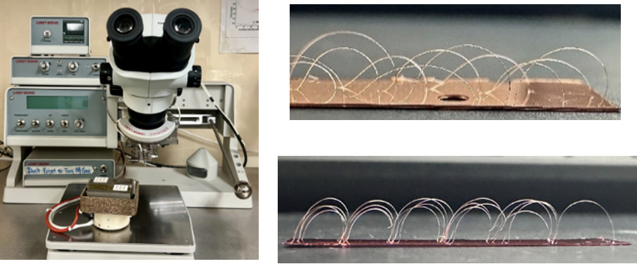
Ultrasonic stitch bonding was performed on both passivated (passivated Cu-LF) and bare (as received Cu-LF) Cu leadframes at room temperature (RT) using a WEST-BOND Manual Wire Bonder with 45° wire feed, as shown in Fig. 2 (left). Before stitch bonding, both leadframe types were pre-annealed at 170 °C and 200 °C for 1, 3, 5, and 10 minutes in air for Al stitch bonding, as shown in Fig. 2 (top right), and PCC stitch bonds on LF after annealing at 200 °C for 5 mins, shown in Fig. 2 (bottom right). Five to fifteen bonds were formed for each condition, with uniform loop height and bond length to ensure reliable pull-strength measurements. Pull testing was performed using an in-house hook setup, in which a tensile force was applied perpendicular to the stitch bond until failure. The corresponding pull strength values were then recorded and compared for analysis. Post-bond failure analysis, including optical imaging with a Keyence VK-X3000 confocal microscope, was performed to determine the wire breakage point (whether from the Cu-LF substrate or the wire neck).
__and_a_series_of_al_wire_(top_right)_and_pcc_.png)
III. Results and Discussion
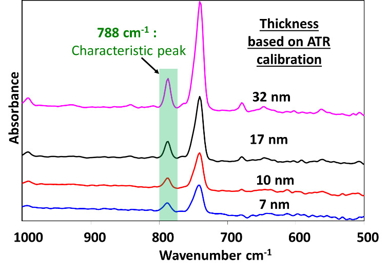
A. Characterization of Cu-selective Passivation Film on Cu-LF substrate
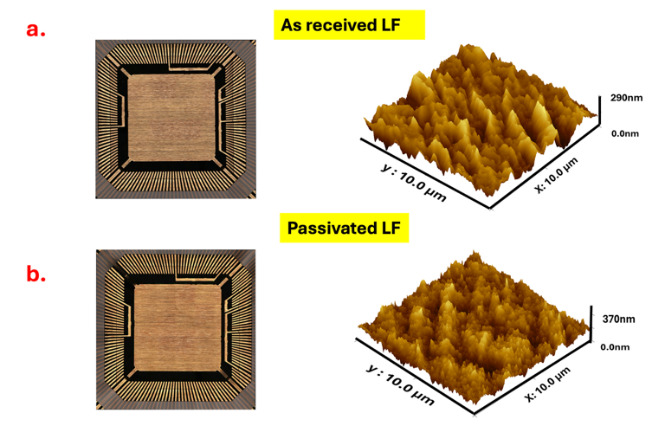
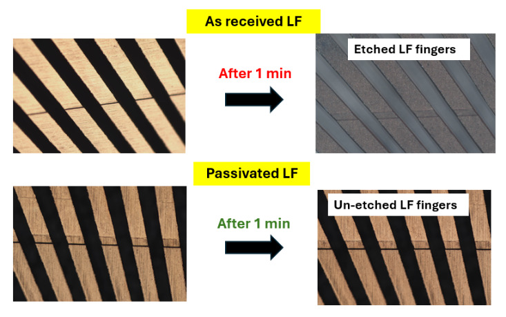
In our prior work (Alptekin et al. 2023), the 788 cm-¹ RAIRS peak, attributed to the characteristic Cu-selective passivation, was established as a chemically distinct and reliable spectral marker for coating thickness, owing to its well-defined peak shape and strong linear correlation with film thickness. Fig. 3 shows representative ATR spectra from passivated Cu-LF substrates, where the progressive increase in peak intensity at 788 cm⁻¹ aligns with increasing film thickness. The explored thickness range of 7 to 32 nm was selected to span the functional window relevant to subsequent reliability studies, allowing us to probe both the threshold of oxidation suppression and bonding interface integrity under elevated-temperature conditions such as 170 °C-200 °C. To rigorously assess the integrity and conformality of the Cu-selective passivation coating, we examined both the nanoscale surface morphology and the localized resistance to chemical etching. An effective conformal barrier must (i) uniformly cover the native asperities of the Cu leadframe without perturbing its underlying microstructure and (ii) suppress direct Cu dissolution even under aggressive acidic Cu etching conditions intentionally designed to attack unprotected bare copper. AFM characterization of the as-received and passivated leadframes (Fig. 4a,b) demonstrates that the coating satisfies these criteria. The arithmetic mean roughness (Ra) increases only modestly from 29.3 ± 4.0 nm (as received) to 44.4 ± 0.1 nm after passivation, while the 3D AFM height maps show that the original microscale asperities and surface texture of the copper are preserved. This is supported by the accompanying optical images, which exhibit nearly identical macroscopic appearance before and after nanoscale passivation coating. The consistent visual texture indicates that the passivation layer forms an ultrathin, uniform film. This layer drapes over the entire Cu surface without planarizing or obscuring its geometric profile. Collectively, the AFM and optical data confirm that the coating provides complete topographical coverage while maintaining the substrate’s intrinsic morphology. These results suggest a conformal coating on the leadframe surface. Building on this morphological evidence, the micro-etching results presented in Fig. 5 provide additional functional validation of coating continuity and robustness. Upon exposure to the CuCl₂/HCl etchant, the as-received leadframe rapidly roughens and darkens, consistent with the expected dissolution and surface degradation of unprotected Cu. In sharp contrast, the passivated leadframe retains its metallic luster and optical uniformity, reflecting the presence of a continuous, protective film analogous to that observed in the AFM measurements. This smooth progression from nanoscale morphology (Fig. 4) to macroscopic chemical performance (Fig. 5) demonstrates that the conformal coating not only replicates the Cu leadframe surface topography but also, defect-free, affords strong protection against localized acidic Cu etching attack.

_as-received_lf_and_(b)_passivated_lf_showing_conformal_coating.png)
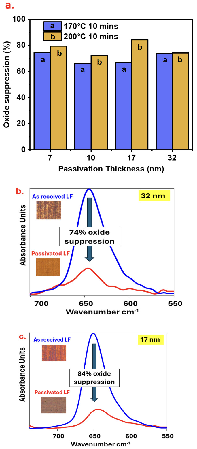
B. Cu-Oxidation Suppression using Passivated Film at Elevated Temperature
Copper surfaces are inherently prone to oxidation when exposed to air, a phenomenon that accelerates significantly at elevated temperatures relevant to microelectronic packaging processes. Specifically, temperatures more than 150 °C facilitate the rapid formation of Cu₂O, the dominant oxide phase below 300 °C (Razali et al. 2018; Lee et al. 2016). In this study, we evaluated the oxidation suppression capabilities of a Cu-selective passivation coating. We utilized Cu leadframe (Cu-LF) edge samples under temperature and time conditions representative of typical wire bonding processes. The Cu-LF substrates were passivated with four distinct film thicknesses: 7 nm, 10 nm, 17 nm, and 32 nm. These samples, along with as-received Cu-LF controls, were air-annealed at 170 °C and 200 °C for durations ranging from 1 to 10 minutes.
To assess the coating’s durability under prolonged thermal exposure, the evaluation focused on samples annealed for a maximum of 10 minutes. Quantitative analysis of oxide suppression confirms that the Cu-selective passivation layer provides robust protection against air oxidation (Fig. 6a). Although all coating thicknesses were effective, the 17 nm film exhibited the most stable performance. It suppressed more than 80% of oxide growth at 200 °C. This trend is supported by ATR-IR monitoring of the 650 cm-1 band (Fig. 6b and 6c). While the as-received Cu-LF control underwent severe oxidation and visible discoloration at 170 °C and 200 °C, the passivated substrates remained chemically stable. Specifically, the 32 nm and 17 nm passivation samples achieved oxide-suppression efficiencies of 74% and 84%, respectively. An efficiency of 84% indicates that the layer successfully blocked the vast majority of oxide growth. This is further evidenced by the spectroscopic data and microscopic insets in Fig. 6(b) and 6(c). Even when the as-received substrate experienced high oxidation levels of 65.1 mAbs, the passivated sample maintained a low profile of 10.3 mAbs. These results demonstrate that the film acts as a robust kinetic barrier. It significantly reduces oxygen diffusion even at elevated manufacturing temperatures of 200 °C.
_oxide_suppression_capability_across_different_coating_thicknesses_at_elevated_temperatur.png)
C. Effect of Cu-Selective Passivation on Al and PCC Stitch Bonding
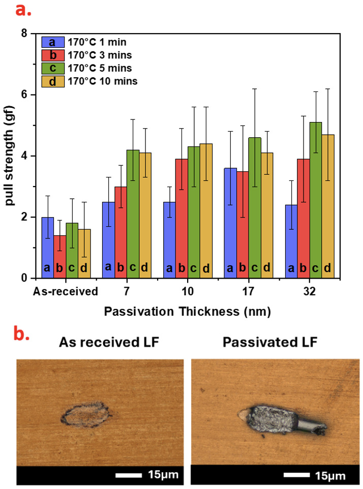
The practical impact of the passivation coating was evaluated by forming stitch bonds using 25 µm Al wire on pre-annealed Cu-LF. The hook-pull method was used to pull the wire stitched onto the Cu-LF surface. The pull strength results demonstrate a clear correlation between thermal oxidation suppression and bonding performance on Cu-LF substrates. Fig. 7(a) shows the post-pull test results. The unprotected as-received Cu-LF exhibited significantly lower pull strength, ranging from 1.4 ± 0.5 gf to 2.0 ± 0.7 gf (1 gf ≈ 9.81 mN). In contrast, stitch bonds formed on the passivated Cu-LF showed markedly improved performance across all pre-annealing durations. The pull strengths for passivated samples ranged from a minimum of 2.5 ± 0.8 gf (7 nm annealed at 170 °C for 1 min) to a maximum of 5.1 ± 1.0 gf (32 nm annealed at 170 °C for 5 mins).
_pull_strength_of_al_stitch_bonds_on_as-received_vs_passivated_cu-lf_after_pre-annealing_.png)
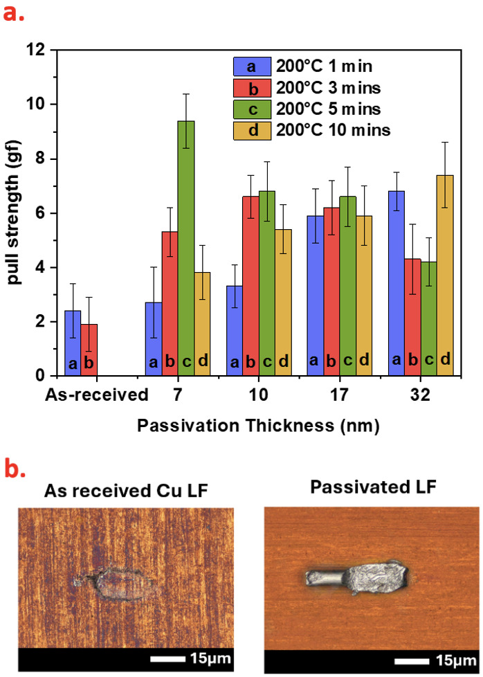
Importantly, these values meet or exceed the minimum bond-strength requirement of 2.5 gf specified by MIL-STD 883E, Method 2011, Test condition D for one mil Al wire bonds (MIL-STD 883E Method 2011.9, Department of Defense Test Methods Standards Microcircuits 1996). The failure modes were classified according to MIL-STD 883 Method 2011. The passivated Cu-LF samples consistently exhibited failure code 2, characterized by wire breakage at the neckdown region of the stitch bond. In contrast, the as-received Cu-LF samples failed under code 4, resulting in bond lift-off from the substrate as clearly evidenced in Fig. 7(b). The protective capability of the passivation layer is most evident at 200 °C, a regime where severe oxidation typically compromises bond integrity. While the as-received Cu-LF rapidly degraded to a critical wire-pull strength of 2.4 ± 1.0 gf after just 1 minute, the passivated samples exhibited remarkable resilience (Fig. 8a). Despite the uncontrollable oxide kinetics characteristic of this temperature, the coatings successfully preserved bondability. Peak pull strengths reached 9.4 ± 1.0 gf after 5 minutes, and adhesion remained robust even under extended 10-minute thermal stress, with values ranging from roughly 5 to 7.4 gf. These results consistently exceed the failure threshold of the uncoated baseline, demonstrating
_pull_strength_of_al_stitch_bonds_on_passivated_vs._as-received_cu-lf_after_200_c_anneal.png)
effective surface stabilization. Fig. 8(b) illustrates the corresponding failure modes. While passivated samples exhibited strong bond adhesion, the as-received Cu-LF failed completely after annealing for 5 and 10 minutes. The thick oxide layer that developed on the as-received Cu-LF prevented adhesion, causing the Al wire to rebound from the surface. This resulted in a high non-stick-on-lead (NSOL) rate, rendering successful stitch bonding is impossible under the applied bonding parameters. Having established the efficacy of the passivation layer in preventing oxide-induced failures and non-stick-on-lead (NSOL) defects during aluminum wire bonding, the study expanded its scope to evaluate the coating’s versatility with harder wire materials. Specifically, the investigation shifted to 25 µm PCC wire. Unlike the room-temperature ultrasonic process used for aluminum, PCC utilizes thermosonic bonding, which necessitates elevated substrate temperatures to induce thermal softening and facilitate atomic diffusion. This requirement inherently subjects the copper leadframe to immediate thermal oxidation during the bonding process. Consequently, before evaluating the reliability of the passivation under these thermosonic conditions, it was essential first to define a stable baseline process. To establish a stable bonding process, iterative experimental trials were conducted to optimize the ultrasonic power, bond force, and bonding time. Achieving an equilibrium between mechanical deformation and ultrasonic energy is crucial for penetrating surface oxides and enabling atomic diffusion.
Unlike standard industrial processes that typically require a forming gas environment (Pequegnat et al. 2010), these bonding experiments were successfully conducted under ambient conditions (22 °C and 50% Relative humidity). The optimized parameters for 125 °C and 200 °C were determined as follows: ultrasonic power of 300-500 units (2.5 W output), bonding force of 20-40 g, and bonding time of 20-80 ms.
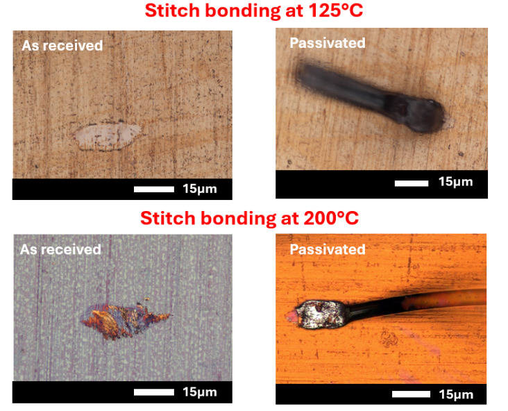
At a bonding temperature of 125 °C, the process window for non-passivated (as-received) Cu leadframes was significantly narrow. Despite ultrasonic power adjustments intended to disrupt surface oxides, control samples exhibited poor interfacial adhesion, yielding a negligible pull strength of 1 gf (Fig. 9 top left). This suggests that the native oxide layer is believed to act as an acoustic barrier, impeding the transfer of ultrasonic energy required for Cu-Cu bond formation. Conversely, the Cu-selective passivated samples exhibited a broad and stable process window. By mitigating surface oxidation, the passivation layer allowed the optimized energy inputs to be directed toward stitch formation rather than oxide removal. Consequently, robust bonding was achieved with average pull strengths of 7 gf (Fig. 9 top right), surpassing the MIL-STD 883E Method 2011 requirements and exceeding the 3.7 gf reported by Qin et al. (2011).

To assess thermal stability, the bonding temperature was elevated to 200 °C with a 5-minute dwell time. Typically, elevated bonding temperatures induce thermal softening in the copper substrate, necessitating reduced ultrasonic power or bonding force to avoid excessive deformation or heel cracking. However, for as-received controls, rapid thermal oxidation at 200 °C negated the advantages of thermal softening. Significant oxide growth led to consistent adhesive failure (lift-off) and low pull strengths of 2 gf (Fig. 9, bottom left), confirming that standard bonding parameters were insufficient to overcome aggressive oxidation kinetics. In contrast, passivated surfaces maintained integrity at 200 °C. The coating’s chemical stability permitted the continued use of the optimized bonding parameters without oxide interference, yielding superior pull strengths in the 6-9 gf range (Fig. 9, bottom right). These results collectively demonstrate that the Cu-selective passivation significantly enhances reliability by mitigating oxidation and ensuring robust bonding across diverse wire types and thermal conditions.
IV. Conclusion
This study successfully demonstrates that an ultrathin (7-32 nm) Cu-selective passivation layer serves as a robust, cost-effective, and environmentally sustainable alternative to traditional Ag plating for copper leadframe packaging. Characterization via ATR spectroscopy and AFM confirmed that the coating grows conformally, preserving the substrate’s topography while providing a dense barrier that effectively suppresses Cu oxide formation at elevated temperatures (200 °C) by over 80%.
The pivotal role of this passivation in enabling reliable interconnection was evident across stitch bonding processes for both aluminum and PCC wire. For as-received Cu leadframes, rapid thermal oxidation acted as an acoustic barrier during PCC bonding at elevated temperatures (125 °C and 200 °C), impeding ultrasonic energy transfer and preventing atomic diffusion. This resulted in negligible pull strengths (< 2 gf) and adhesive lift-off failures. Notably, the passivated leadframes maintained a pristine interface, allowing ultrasonic energy to facilitate Cu-Cu bonding in ambient conditions, resulting in robust bond formation with pull strengths significantly exceeding MIL-STD 883E requirements (up to 9.4 gf for Al and 9 gf for PCC) and a favorable shift in failure mode to cohesive wire neck breakage. Ultimately, this work establishes that Cu-selective passivation widens the process window for next-generation Cu-Cu stitch bonding, offering a high-reliability solution that eliminates the economic and environmental burdens of noble metal plating.
Acknowledgment
We gratefully acknowledge the financial support from the University of North Texas for this study. We also thank NXP Semiconductors for providing the substrate materials. Special thanks to Dr. Varughese Mathew for his valuable discussions and insightful contributions.